
1960s Wiring Diagram Effects Pedal
Wiring diagram electric guitar diagrams and schematics with. 2) find the input jack terminal tip, and unsolder and disconnect only the short wire that connects to the circuit input (marked #1 on the circuit board diagram).

PREWIRED KIT JAZZ BASS JBass 19601962 stacked Pots Fender jazz bass, Diy guitar pedal
Everything works except that when you turn up the volume pot all the way it cuts out.

1960s wiring diagram effects pedal. I suggest mentioning this to your significant. 1960's style wiring harness for fender jazz bass! The diagrams of how to connect the pedals at amps.
I have a bit of wiring experience doing pickup swaps and putting together a telecaster, but this is way above my pay grade. Or as tb's wiring guru line6man draws them, like this: I picked up this way cool 1960s domino spartan jazzmaster copy not long ago:
Pedal wiring guide by pcb guitar mania document version 1.0v, 16th march 2019 2 2. Just ensure you have the transistor wires connected the right way. Vox made a variety of boosters that were meant to be plugged directly… read more »
This is my first pedal so i'm a tad nervous about it. The pickup has lots of output for this type and vintage. Created by an effects unit, such as a delay pedal or effect fed back into a mixing console.
They give the body and paint a real workout, and leave out the controls for the most part. The pots are cts' finest 500k models with brass posts and shafts. Wiring the switch connections is fiddly, and best done before pedal assembly begins.
Internal wiring and components led add schematic kb. Thomas organ patented the wah circuit design but by the time the patent was granted, there were already dozens of copies of the pedal in the market. But in the diagram it shows each pot going to a vero board so here's the question.
First of all, please excuse the outstanding quality of my diagram. A treble booster is an effects unit used by guitarists to boost volume and especially the high end of their tonal spectrum, and was popular mostly during the 1960s. You look as some of these high priced relic basses, and the hardware still looks relatively new!
The feedback can be controlled by using the fader to determine a volume level. Aluminum is a great conductor and was relatively cheap, so it was the obvious choice. Eventually a loose jack may twist the wiring until the connection is broken.
Loose wiring, cold solder joints, broken connections and burnt insulation can all cause problems. Relentless™ middle | dimarzio here is the schematic diagram of the circuit (figure 4) figure 4. This method does not always eliminate potential switching problems, but it gets us there most of the time.
Back off a tiny bit and it works fine. This is the original wiring: Sears silvertone model 319 acoustic guitar from 1960s.
The base wire will always be in the centre and the emitter wire may be marked by a little tag on the case. I did not mean to intimidate anybody. Cts, mallory, pure tone, gavitt, new!basically the same as my standard model that has orange drop caps, but here we upgrade to mallory caps, and pure tone jackthis wiring harness ships via usps priority mail want to modify your mod.
I am looking for a wiring diagram for a latching switch pedal with an led and 9v wall wart adapter, so i can turn the. The following scheme diagram is the circuit diagram of vox treble booster effect. In this post, i want to show you how to make a good wiring, and what you can do to avoid mistakes.
Before the 1960s, copper was the most common material used in household wiring. This is standard for amps and effects pedals too. But a massive shortage left costs for this metal way too high for the average homeowner.
Order switch explained selecting the order of through two effects on the same enclosure is an easy task with our order switch pcb. 2) find the input jack terminal tip, and unsolder. The caps we use in these harnesses are genuine vintage sprague black beauties from the 60s.
We offer a variety of pedals that can be placed in many different here are some common effect placement suggestions for pedalboard setups in general. Hello, i am trying to build the gaspedal dumbbell pedal with the dual effects offboard wiring diagram. Unsolder and remove it here as well.
As a result, builders turned to aluminum wiring in new construction. Are these separate boards from the main board or are they the same or different boards entirely because i. Channel/effects footswitch pedal wiring diagram.got one?
I've been looking all over the place but i can't find one. You are now and expert in true bypass wiring for guitar pedals.

Electrical Wiring Pleasant Diy Guitar Pedal Projects Offboard Soldering Along Distortion Plus

Pin by jonitto on Diy guitar pedal Diy guitar pedal, Simple circuit, Diagram

Build Your Own Guitar Distortion Pedal Circuit Distortion pedal, Guitar distortion pedal
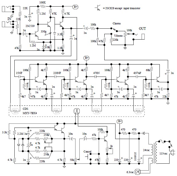
Univibe Effect Pedal Circuit Schematic

Stompbox Guitar Pedal Wiring Diagram Diy guitar pedal, Guitar pedals, Guitar diy
pedalboard wiring The Gear Page

stompbox wiring Google Search Diy guitar pedal, Guitar cable, Guitar pedals

WIRING DIAGRAMS GUITAR EFFECTS PEDALS Auto Electrical Wiring Diagram

DIGITAL DELAY Diy guitar pedal, Audio amplifier, Electronics circuit

Pin on GuitarPedal\DIY

Pin em Mainan anak
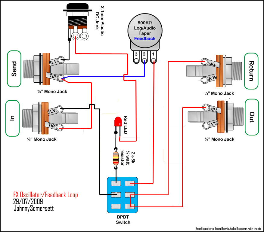
NDIYPD New DIY Pedal Day Feedback Looper/FX Oscillator

Pin on Pedal
> circuits > vintage fuzz box l30222 Next.gr

guitar pedal wiring diagrams auto wiring diagram preview guitarpedals Diy guitar pedal

Pin by Mikelebro on Guitar pedals Guitar pedals, Pedal, Sheet music

DIY ABY Amp & Signal Switcher Guitar Pedal DIY Guitar Effects Pedals
Guitar Effects Pedal Building Offboard Wiring Demystified mklec blog Diy guitar pedal

e63d192d81fe94312606c4335c6ade7c.png (1273×575) Diy guitar pedal, Guitar pedals, Guitar diy