
Where Does Yellow Wire Go On 7 Way Plug
Having the wires backward will cause problems. As the name implies, they use four wires to carry out the vital lighting functions.

7 Way Plug Wiring Diagram Trailer Wiring Sample
The red wire is for the 12 volt ignition, which can be attached to the stereo.

Where does yellow wire go on 7 way plug. Color of wire (light blue with yellow tracer) gauge of wire (18 gauge) part of main circuit (varies depending on equipment) main circuit identification. The yellow wire from your harness will run to the left turn signal red wire. What color wires go together on a trailer?
We are going to do our best to simplify that, mainly with a good, color coded diagram. Figure 2 ± wire color code charts figure 3 ± circuit identification. All three of these wires need to be attached to the receptacle.
Each connects to a different function: Main circuits only and does not show the secondary codes that may apply to some models. We do this on all of our trailers and our customers trailers and.
If you are able to look at a manufacturer's diagram of the alternator's connectors, the wire that slides over pin 1 of the alternator leads to the positive (+) connection on the vehicle's battery and senses voltage. They also provide a wire for a ground connection. The blue wire connects to the neutral terminal on the left of the plug.
This wire, once attached to the stereo, will help ground it. What wires go on a. White wire to common or chassis ground.
The red wire is the turn signal wire and will be run to the green wire of your harness if its the right turn signal side, and the black wire will run to the brown wire of your harness. Green wire to right turn signal/brake light. Green = right turn signal & right brake light.
The rest you can ignore. The first this to do is attach the bare wire to the back of the electrical box (wrap around one of the screws) but leave enough of a tail to attach the the green or blackish screw at the bottom of the plug. This connector is manufactured so it may be inserted into the connector socket on the alternator one way only.
Brown = tail lights, side markers and running lights (see brown wire notes below.) 3. The pollack plug has wire color suggestions on it. For more info, see car stereo installation:
Inside the plug are three terminals: Hold the plug so that you are looking at it from the rear with the hinge for the front access door on top. Loosen the screws for the six outside terminals.
The four wires control the turn signals, brake lights and taillights or running lights. Electrical dummy needs help wiring new lowrance hds 7 power cord. Yellow = left turn signal & left brake light 4.
Yellow wire to the left turn signal/brake light. Download the guide below, print it and keep it in your toolbox for future reference. 7 way plug wiring diagram standard wiring* post purpose wire color tm park light green (+) battery feed black rt right turn/brake light brown lt left turn/brake light red s trailer electric brakes blue gd ground white a accessory yellow this is the most common (standard) wiring scheme for rv plugs and the one used by major auto manufacturers today.
Brown wire to the tail or parking lights. The yellow wire is the 12 volt battery wire, which should also be attached to the stereo for power. 6 way plug wiring diagr am standard wiring* post purpose wire color tm park lights brown gd ground black (or white) s trailer brakes blue lt left turn/brake light yellow rt right turn/brake light green a accessory red the most common variances on this diagram will be the (blue/brake) & (red/acc.) wires will be inverted.
The final wire, the black wire, is the ground wire. 7 way plug wiring color/diagram But as long as nothing is drawing power on that circuit it would be fine to leave hot all the time.
The colors seem to hold out, match with yellow left over to go to center (auxiliary). The brown wire goes to the live terminal, which is on the right of the plug neutral : These four colored wires make up your trailer's wiring system.
Please see the trailer wiring diagram and connector application chart below.
for Tool Sewing Machine Hand Machine, Sewing for Threaders

We Have Covered Everything You Need To Know About

Home networking explained, part 3 Taking control of your
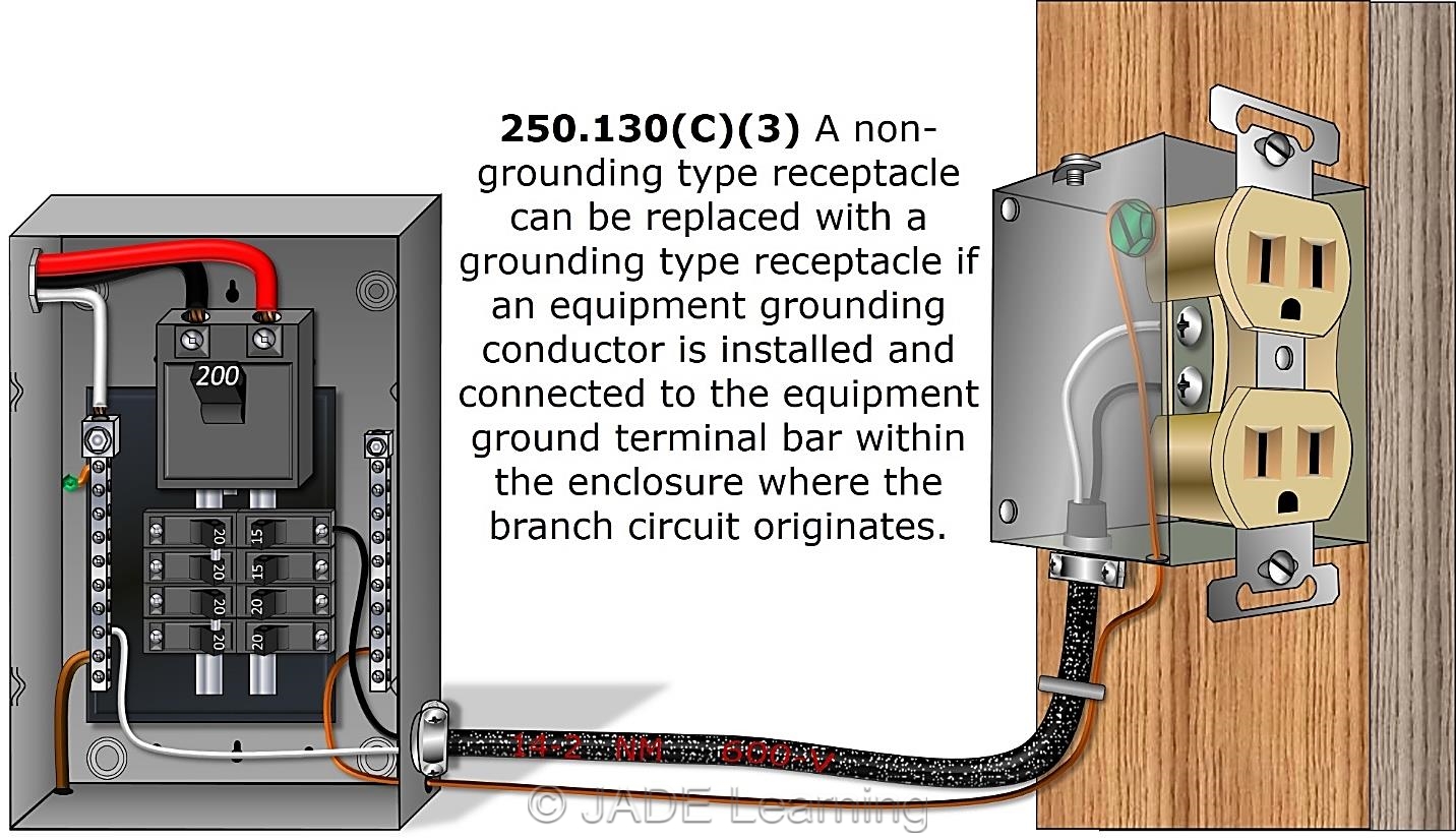
How To Ground An Outlet With Only Two Wires
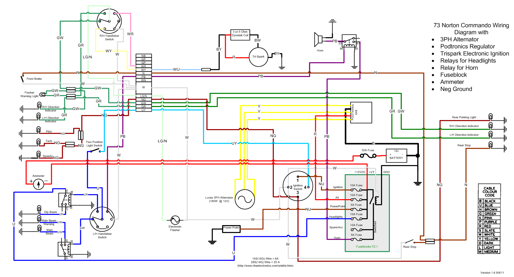
Interpretation Of Circuit And Wiring Diagrams Pdf 4K

what gauge wire are trailer lights DHNX Wiring Diagram
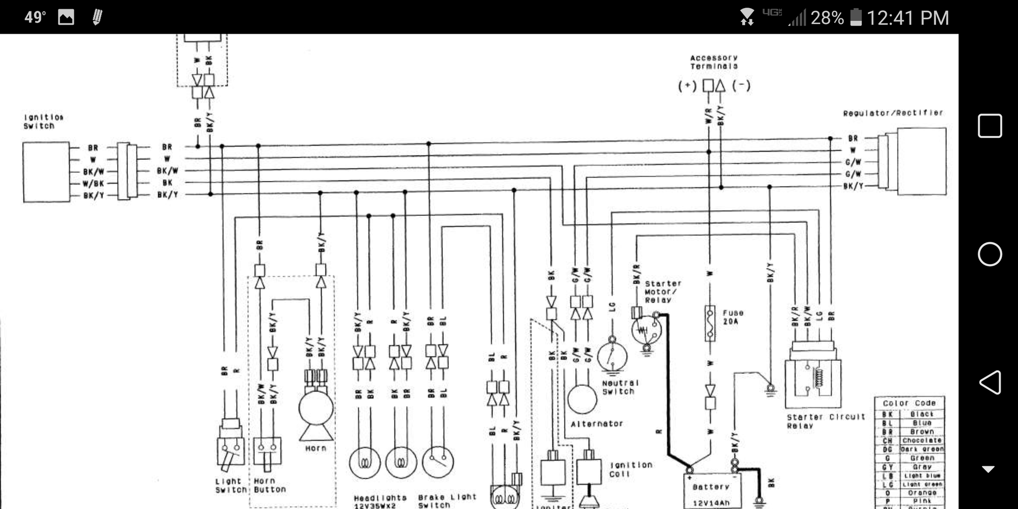
Kawasaki Mule Kaf300c Wiring Diagram Wiring Diagram

wiring colours australia IOT Wiring Diagram
Interpretation Of Circuit And Wiring Diagrams Pdf 4K

what gauge wire are trailer lights DHNX Wiring Diagram

Terminal Block DIY Wire Connector Push In Solderless

Does anyone else get this issue when turning on alarms

Terminal Block DIY Wire Connector Push In Solderless

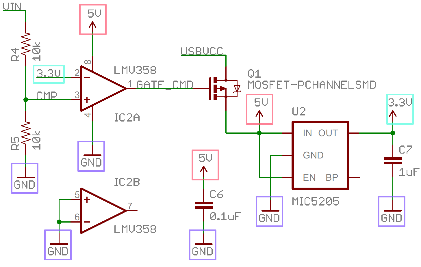
Easiest way for one to one connections Schematic KiCad

for Tool Sewing Machine Hand Machine, Sewing for Threaders

Interpretation Of Circuit And Wiring Diagrams Pdf 4K
:max_bytes(150000):strip_icc()/ElectricalWiring-1152863-2143c6964ddd48e2ad1fb664c296561e.jpg)
home electrical wire colors Wiring Diagram and Schematics

wiring colours australia IOT Wiring Diagram
How To Ground An Outlet With Only Two Wires
